Final Electronics Design
How I Designed and Milled My Custom PCB with Seeed XIAO ESP32C3
Introduction
Hey there! I'm excited to share how I designed my own electronics board using KiCad, and then milled it with the SRM-20 machine. My board includes a Seeed XIAO ESP32C3 module and some pin headers. I'll walk you through the whole process, from design to milling. Let's dive in!
What You'll Need
- KiCad: For designing the PCB.
- Seeed XIAO ESP32C3: The star of the show, a powerful microcontroller module.
- SRM-20: The milling machine.
- Mods Project: A web tool for managing PCB milling.
- 1/64 inch milling tool: For cutting the traces.
- 1/32 inch milling tool: For cutting the edges.
- PCB material: A copper-clad board, perfect for milling.
Steps to Create Your Custom PCB
1. Designing the PCB in KiCad
Start a New Project:
- Open KiCad and start a new project. Give it a cool name.
Create the Schematic:
- Open the schematic editor (Eeschema).
- Add the Seeed XIAO ESP32C3 and the pin headers.
- Connect everything with wires and add any extra components you need.
- Annotate your schematic, assign footprints to components, and run an electrical rules check.
Design the PCB Layout:
- Open the PCB editor (Pcbnew).
- Import the netlist or update the PCB from the schematic.
- Place your components on the board and route the traces.
- Define the board edges.
-
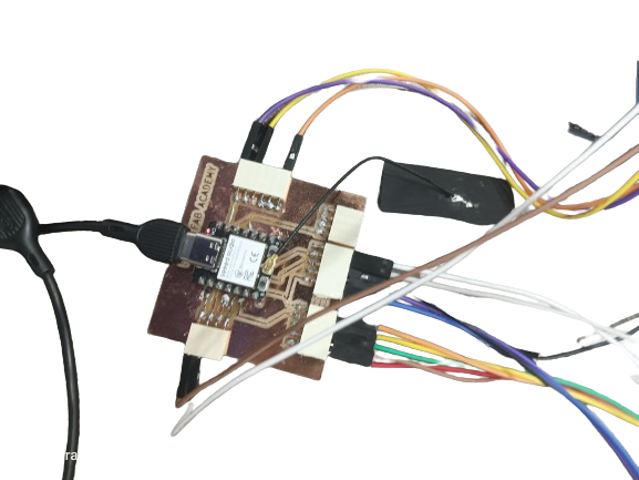
Here I have designed my own pcb to the final project that I am using seeed xiao esp32c3 and pin headers to help me to onnect the wires.
For more details for design see Electronics design week.
2. Exporting SVG Files
Get Ready for Export:
- Make sure your PCB design is finalized.
Export to SVG:
- In Pcbnew, go to
File>Plot. - Choose
SVGas the output format. - Select the layers you need (like the copper layer and edge cuts).
- Hit
Plotto create the SVG files.
- In Pcbnew, go to
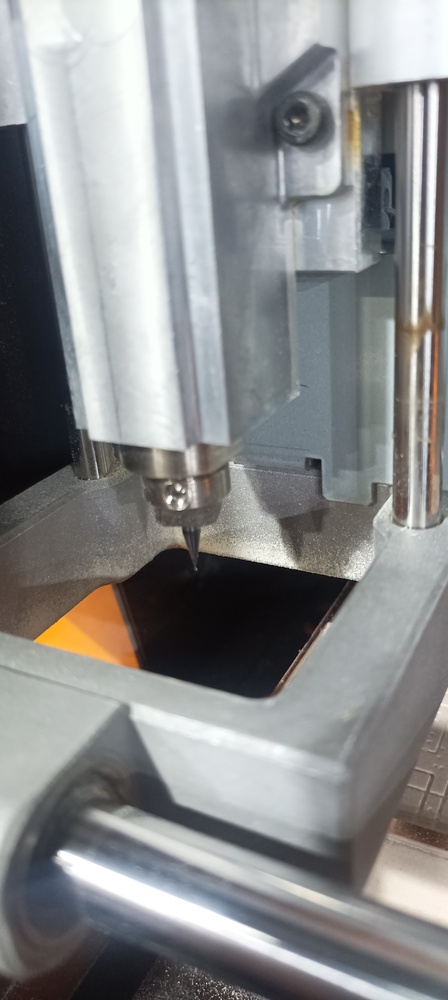
3. Milling with SRM-20
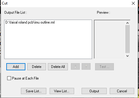
Import SVG Files into Mods Project:
- Open the Mods Project in your browser.
- Choose the SRM-20 milling module.
-
Set Up Milling:
- Load your SVG files into Mods.
- Set the toolpath for the 1/64 inch tool to cut the traces.
- Set the toolpath for the 1/32 inch tool to cut the edges.
-
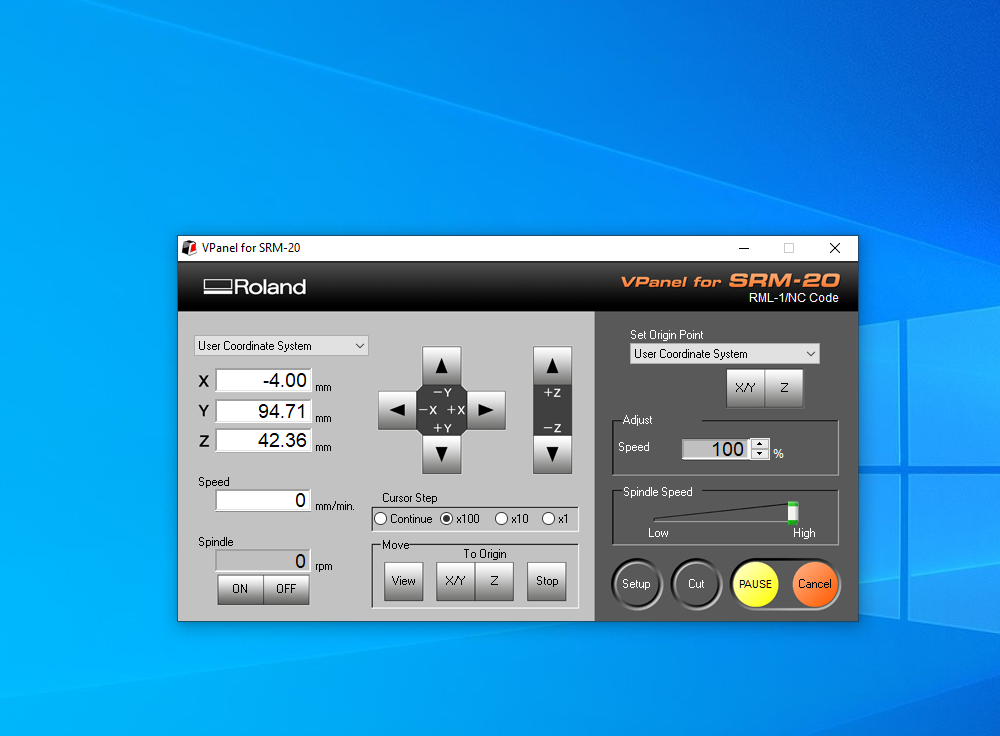
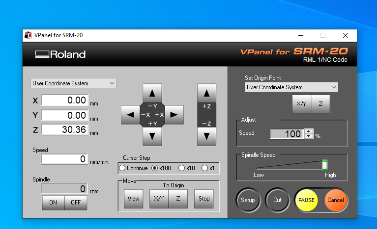
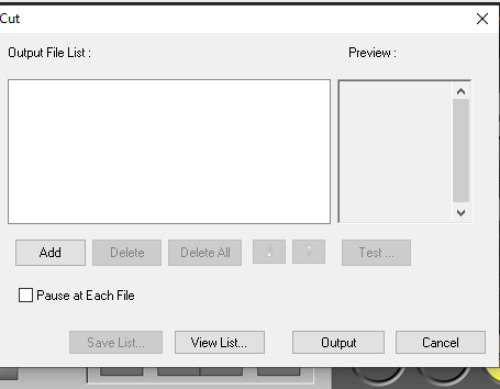
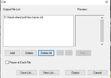
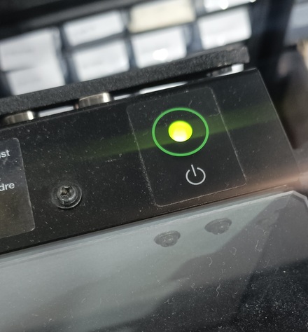
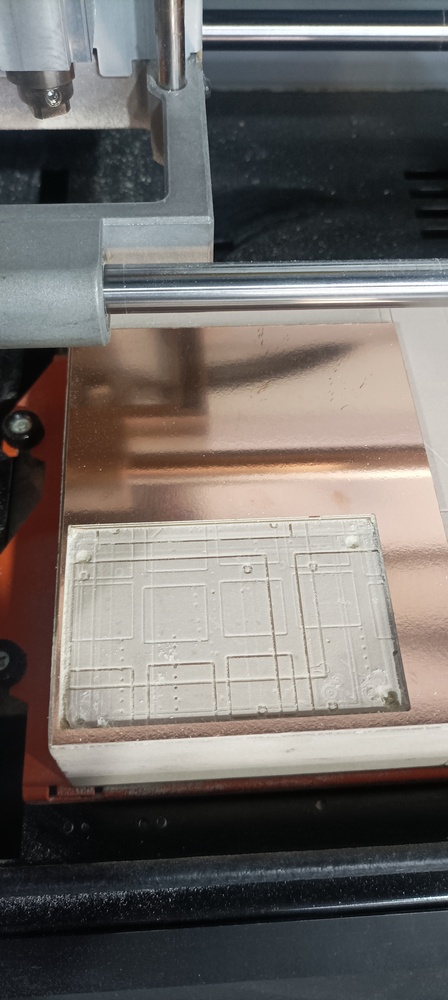
Mill Your PCB:
- Secure your PCB material on the SRM-20.
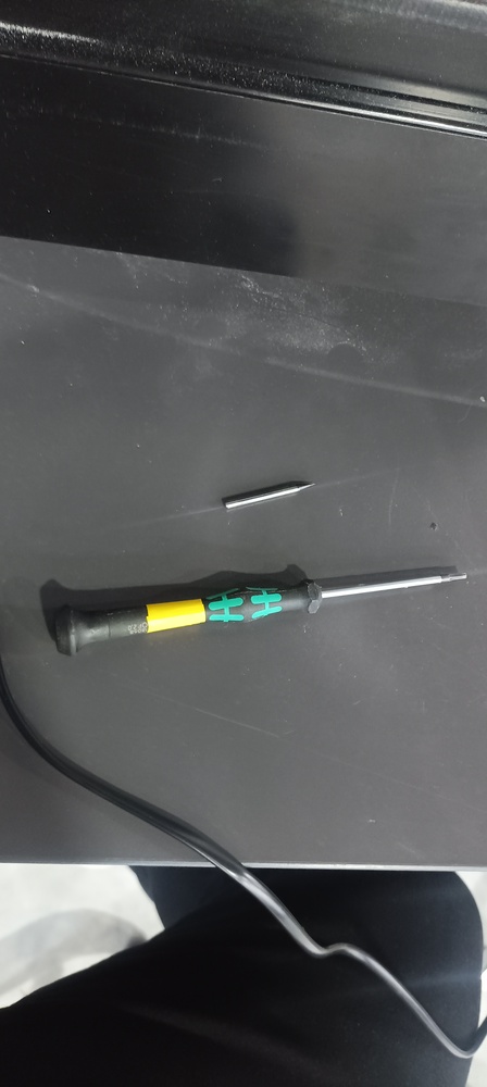
- Load the 1/64 inch tool and cut the traces.
- Switch to the 1/32 inch tool and cut the edges.
4. Finish Up
Inspect Your PCB:
- Check for any issues or rough edges.
- Use a multimeter to make sure all the connections are good.
-

Assemble Your Board:
- Solder the Seeed XIAO ESP32C3 and pin headers onto the board.
- Test your board with a simple program to make sure everything works.
Conclusion
And that's it! You've designed a custom PCB with KiCad, exported it as SVG files, and milled it with the SRM-20. This process is great for rapid prototyping and making your own custom electronics. Happy building!
Tilt Angle Monitor with Linear Actuator Control
I'm excited to share my latest project, which involves using an ESP32 microcontroller to monitor tilt angles using two MPU6050 sensors and control a linear actuator via Blynk. Here's a step-by-step guide to how I set it all up.
For more about how to use Blynk app and website feel free to go to Interface and Application Programming
What You'll Need:
- ESP32 board (I used the Seeed Xiao ESP32C3)
- Two MPU6050 accelerometer and gyroscope sensors
- Linear actuator
- WiFi network
- Breadboard and jumper wires
Software:
- Arduino IDE
- Blynk app on your smartphone
- Blynk library in the Arduino IDE
Step 1: Hardware Setup
Connecting the MPU6050 Sensors to the ESP32:
- VCC to 3.3V
- GND to GND
- SCL to GPIO 07
- SDA to GPIO 06
- Note: The first MPU6050 should have the address 0x68 (AD0 pin connected to GND), and the second MPU6050 should have the address 0x69 (AD0 pin connected to VCC).
Connecting the Linear Actuator to the ESP32:
- Connect the extend pin of the actuator to GPIO 2.
- Connect the retract pin of the actuator to GPIO 3.
Step 2: Setting Up the Blynk App
Creating a New Template:
- Open the Blynk app and log in.
- Go to the "Templates" section.
- Create a new template and name it "Tilt Angle Monitor with Linear".
- Make sure to note down the
Template IDandAuth Tokenthat Blynk gives you.
Adding Datastreams:
- Add the following datastreams to your template:
V1for X angle of Sensor 1V2for Y angle of Sensor 1V3for Z angle of Sensor 1V4for X angle of Sensor 2V5for Y angle of Sensor 2V6for Z angle of Sensor 2V7for Extend buttonV8for Retract button
- Add the following datastreams to your template:
Creating a Web Dashboard:
- Add widgets to the web dashboard corresponding to each of the virtual pins. You can use sliders or buttons for the control pins and value displays for the angles.
Step 3: Coding and Uploading
Install Required Libraries:
- Open the Arduino IDE and install the following libraries:
Adafruit MPU6050Adafruit Unified SensorBlynkWiFi
- Open the Arduino IDE and install the following libraries:
Updating the Code:
- Copy and paste the following code into a new Arduino sketch:
cpp#include <Wire.h>
#include <Adafruit_MPU6050.h>
#include <Adafruit_Sensor.h>
#define BLYNK_TEMPLATE_NAME "Tilt Angle Monitor With Linear"
#define BLYNK_AUTH_TOKEN "your_blynk_auth_token"
#define BLYNK_TEMPLATE_ID "your_template_id"
#define BLYNK_PRINT Serial
#include <WiFiClient.h>
#include <BlynkSimpleEsp32.h>
const int extendPin = 2; // Pin to extend the actuator
const int retractPin = 3; // Pin to retract the actuator
char auth[] = "your_blynk_auth_token"; // Your Blynk Auth Token
char ssid[] = "your_wifi_ssid";
char pass[] = "your_wifi_password";
// Create MPU6050 instances with different I2C addresses
Adafruit_MPU6050 mpu1;
Adafruit_MPU6050 mpu2;
int buttonState1 = HIGH; // Initial state for button 1
int buttonState2 = HIGH; // Initial state for button 2
void setup() {
Serial.begin(115200);
while (!Serial) delay(10); // wait for serial port to open on native USB devices
Wire.begin(6, 7); // Initialize I2C with SDA on GPIO 06 and SCL on GPIO 07
// Initialize MPU6050 sensor 1
if (!mpu1.begin(0x68)) {
Serial.println("Failed to find MPU6050 chip 1");
while (1) {
Serial.println("chip 1 not found");
delay(10);
}
}
mpu1.setAccelerometerRange(MPU6050_RANGE_2_G);
mpu1.setGyroRange(MPU6050_RANGE_250_DEG);
mpu1.setFilterBandwidth(MPU6050_BAND_21_HZ);
// Initialize MPU6050 sensor 2
if (!mpu2.begin(0x69)) {
Serial.println("Failed to find MPU6050 chip 2");
while (1) {
Serial.println("Failed to find MPU6050 chip 2");
delay(10);
}
}
mpu2.setAccelerometerRange(MPU6050_RANGE_2_G);
mpu2.setGyroRange(MPU6050_RANGE_250_DEG);
mpu2.setFilterBandwidth(MPU6050_BAND_21_HZ);
pinMode(extendPin, OUTPUT);
pinMode(retractPin, OUTPUT);
// Setup PWM channels
ledcSetup(0, 5000, 8); // Channel 0, 5kHz, 8-bit resolution
ledcSetup(1, 5000, 8); // Channel 1, 5kHz, 8-bit resolution
ledcAttachPin(extendPin, 0); // Attach extend pin to channel 0
ledcAttachPin(retractPin, 1); // Attach retract pin to channel 1
Blynk.begin(auth, ssid, pass); // Connect to Blynk
Serial.println("Setup complete");
}
void loop() {
Blynk.run(); // Run Blynk
// Read and print accelerometer and gyroscope values for sensor 1
sensors_event_t a1, g1, temp1;
mpu1.getEvent(&a1, &g1, &temp1);
float angleX1 = atan2(a1.acceleration.y, a1.acceleration.z) * 180 / PI;
float angleY1 = atan2(a1.acceleration.x, a1.acceleration.z) * 180 / PI;
float angleZ1 = atan2(a1.acceleration.x, a1.acceleration.y) * 180 / PI;
Blynk.virtualWrite(V1, angleX1);
Blynk.virtualWrite(V2, angleY1);
Blynk.virtualWrite(V3, angleZ1);
// Read and print accelerometer and gyroscope values for sensor 2
sensors_event_t a2, g2, temp2;
mpu2.getEvent(&a2, &g2, &temp2);
float angleX2 = atan2(a2.acceleration.y, a2.acceleration.z) * 180 / PI;
float angleY2 = atan2(a2.acceleration.x, a2.acceleration.z) * 180 / PI;
float angleZ2 = atan2(a2.acceleration.x, a2.acceleration.y) * 180 / PI;
Blynk.virtualWrite(V4, angleX2);
Blynk.virtualWrite(V5, angleY2);
Blynk.virtualWrite(V6, angleZ2);
}
// Handler for virtual pin V7 (extend button)
BLYNK_WRITE(V7) {
buttonState1 = param.asInt(); // Get the value of the virtual button
debounceAndControlActuator();
}
// Handler for virtual pin V8 (retract button)
BLYNK_WRITE(V8) {
buttonState2 = param.asInt(); // Get the value of the virtual button
debounceAndControlActuator();
}
void debounceAndControlActuator() {
// Control linear actuator
if (buttonState1 == HIGH && buttonState2 == LOW) {
// Extend actuator
Serial.println("Extending actuator");
ledcWrite(0, 255); // Full speed extend
ledcWrite(1, 0); // Stop retract
}
else if (buttonState1 == LOW && buttonState2 == HIGH) {
// Retract actuator
Serial.println("Retracting actuator");
ledcWrite(0, 0); // Stop extend
ledcWrite(1, 255); // Full speed retract
}
else {
// Stop actuator
Serial.println("Stopping actuator");
ledcWrite(0, 0); // Stop extend
ledcWrite(1, 0); // Stop retract
}
}
- Uploading the Code:
- Connect your ESP32 board to your computer.
- Select the correct board and port in the Arduino IDE.
- Upload the code to your ESP32 board.
Step 4: Using the Blynk App
Opening the Blynk App:
- Log in to your account and navigate to the project you created.
Adding Widgets:
- Add Value Displays for
V1,V2,V3,V4,V5, andV6to display the tilt angles. - Add Buttons for
V7(Extend) andV8(Retract).
- Add Value Displays for
And that's it! Now you should be able to monitor the tilt angles from both MPU6050 sensors and control the linear actuator using the Blynk app. This setup is perfect for projects that need real-time monitoring and remote control. Happy building!
Purpose of the Code
This code is for an IoT project using a Seeed XIAO ESP32C3 microcontroller. It reads data from two MPU6050 sensors and controls a linear actuator based on commands from a Blynk app. The data from the sensors (like tilt angles) is sent to the Blynk app, where you can also control the actuator's movements.
Key Components
- MPU6050 Sensors: These sensors measure acceleration and gyroscope data.
- Seeed XIAO ESP32C3: A tiny microcontroller that reads data from the sensors, processes it, and sends it to Blynk.
- Linear Actuator: A device that can extend or retract based on commands.
- Blynk: An IoT platform that allows you to control devices and monitor data through a mobile app or web dashboard.
Code Breakdown
Libraries and Definitions
cpp#include <Wire.h>
#include <Adafruit_MPU6050.h>
#include <Adafruit_Sensor.h>
#include <WiFiClient.h>
#include <BlynkSimpleEsp32.h>
#define BLYNK_TEMPLATE_ID "TMPL6qNzlVErN"
#define BLYNK_TEMPLATE_NAME "Tilt angle monitor with linear"
#define BLYNK_AUTH_TOKEN "kJCnfOg6wQy0ZGKHVdSgkQiPDmVMBb9B"
#define BLYNK_PRINT Serial
- These lines include the necessary libraries for the sensors, Wi-Fi, and Blynk.
- The Blynk template ID and authentication token are defined for connecting to the Blynk cloud.
Pin Definitions and Wi-Fi Credentials
cppconst int extendPin = 2;
const int retractPin = 3;
char auth[] = "kJCnfOg6wQy0ZGKHVdSgkQiPDmVMBb9B";
char ssid[] = "Redmi Note 10 5G";
char pass[] = "Fnsama19999";
- Defines the pins for extending and retracting the actuator.
- Sets up the Wi-Fi credentials for connecting to the network.
Initializing Sensors
cppAdafruit_MPU6050 mpu1;
Adafruit_MPU6050 mpu2;
int buttonState1 = HIGH;
int buttonState2 = HIGH;
- Creates instances of the MPU6050 sensors.
- Initializes button states.
Setup Function
cppvoid setup() {
Serial.begin(115200);
Wire.begin();
// Initialize MPU6050 sensor 1
if (!mpu1.begin(0x68)) {
Serial.println("Failed to find MPU6050 chip 1");
while (1) {
Serial.println("chip 1 not found");
delay(10);
}
}
mpu1.setAccelerometerRange(MPU6050_RANGE_2_G);
mpu1.setGyroRange(MPU6050_RANGE_250_DEG);
mpu1.setFilterBandwidth(MPU6050_BAND_21_HZ);
// Initialize MPU6050 sensor 2
if (!mpu2.begin(0x69)) {
Serial.println("Failed to find MPU6050 chip 2");
while (1) {
Serial.println("Failed to find MPU6050 chip 2");
delay(10);
}
}
mpu2.setAccelerometerRange(MPU6050_RANGE_2_G);
mpu2.setGyroRange(MPU6050_RANGE_250_DEG);
mpu2.setFilterBandwidth(MPU6050_BAND_21_HZ);
pinMode(extendPin, OUTPUT);
pinMode(retractPin, OUTPUT);
// Setup PWM channels
ledcSetup(0, 5000, 8);
ledcSetup(1, 5000, 8);
ledcAttachPin(extendPin, 0);
ledcAttachPin(retractPin, 1);
Blynk.begin(auth, ssid, pass, "blynk.cloud", 80);
Serial.println("Setup complete");
}
- Initializes serial communication for debugging.
- Sets up the I2C communication for the sensors.
- Configures each MPU6050 sensor (addresses, ranges, and bandwidth).
- Sets the pins for the actuator as outputs and configures PWM channels.
- Connects to the Blynk cloud using your Wi-Fi credentials.
Loop Function
cppvoid loop() {
Blynk.run();
// Read and print accelerometer and gyroscope values for sensor 1
sensors_event_t a1, g1, temp1;
mpu1.getEvent(&a1, &g1, &temp1);
float angleX1 = atan2(a1.acceleration.y, a1.acceleration.z) * 180 / PI;
float angleY1 = atan2(a1.acceleration.x, a1.acceleration.z) * 180 / PI;
float angleZ1 = atan2(a1.acceleration.x, a1.acceleration.y) * 180 / PI;
Blynk.virtualWrite(V1, angleX1);
Blynk.virtualWrite(V2, angleY1);
Blynk.virtualWrite(V3, angleZ1);
// Read and print accelerometer and gyroscope values for sensor 2
sensors_event_t a2, g2, temp2;
mpu2.getEvent(&a2, &g2, &temp2);
float angleX2 = atan2(a2.acceleration.y, a2.acceleration.z) * 180 / PI;
float angleY2 = atan2(a2.acceleration.x, a2.acceleration.z) * 180 / PI;
float angleZ2 = atan2(a2.acceleration.x, a2.acceleration.y) * 180 / PI;
Blynk.virtualWrite(V4, angleX2);
Blynk.virtualWrite(V5, angleY2);
Blynk.virtualWrite(V6, angleZ2);
}
- Continuously runs the Blynk process to keep the device connected.
- Reads accelerometer and gyroscope data from both sensors.
- Calculates the tilt angles (X, Y, Z) for each sensor and sends this data to the Blynk app using virtual pins.
Blynk Handlers for Buttons
cppBLYNK_WRITE(V7) {
buttonState1 = param.asInt();
debounceAndControlActuator();
}
BLYNK_WRITE(V8) {
buttonState2 = param.asInt();
debounceAndControlActuator();
}
- These functions are called when the virtual buttons in the Blynk app are pressed.
- They update the button states and call the function to control the actuator.
Actuator Control Function
cppvoid debounceAndControlActuator() {
if (buttonState1 == HIGH && buttonState2 == LOW) {
Serial.println("Extending actuator");
ledcWrite(0, 255);
ledcWrite(1, 0);
}
else if (buttonState1 == LOW && buttonState2 == HIGH) {
Serial.println("Retracting actuator");
ledcWrite(0, 0);
ledcWrite(1, 255);
}
else {
Serial.println("Stopping actuator");
ledcWrite(0, 0);
ledcWrite(1, 0);
}
}
- Controls the actuator based on the button states.
- If the extend button is pressed, it extends the actuator.
- If the retract button is pressed, it retracts the actuator.
- If neither or both buttons are pressed, it stops the actuator.
Summary
The code configures the Seeed XIAO ESP32C3 to read sensor data from two MPU6050 sensors and control a linear actuator based on input from a Blynk app. It sends sensor data (tilt angles) to the Blynk app and allows you to extend or retract the actuator using virtual buttons in the app. The setup ensures compatibility with the Seeed XIAO ESP32C3 and maintains the functionality described previously.